Bearing Plates
To resist a beam reaction, the minimum bearing length N in the direction of the beam span for a bearing plate is deter- mined by equations for prevention of local web yielding and web crippling. A larger N is generally desirable but is limited by the available wall thickness.
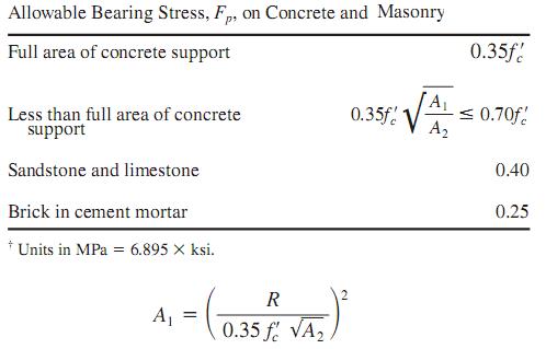
When the plate covers the full area of a concrete support, the area, in 2 (mm 2 ), required by the bearing plate is
A 1= R/0.35f‘c
Where
R=beam reaction, kip (kN),
f ‘c= specified compressive strength of the concrete, ksi (MPa).
When the plate covers less than the full area of the concrete support, then, as determined by following table

where A2= full cross-sectional area of concrete support, in2(mm2 ).
Where
R=beam reaction, kip (kN),
f ‘c= specified compressive strength of the concrete, ksi (MPa).
When the plate covers less than the full area of the concrete support, then, as determined by following table
where A2= full cross-sectional area of concrete support, in2(mm2 ).
With N established, usually rounded to full inches (millimeters), the minimum width of plate B, in (mm), may be calculated by dividing A1 by N and then rounded off to full inches (millimeters), so that BN >=A1. Actual bearing pressure fp, ksi (MPa), under the plate then is
fp=R/BN
fp=R/BN
The plate thickness usually is determined with the assumption of cantilever bending of the plate:

where
t=minimum plate thickness, in (mm)
k=distance, in (mm), from beam bottom to top of web fillet
Fb= allowable bending stress of plate, ksi (MPa)
where
t=minimum plate thickness, in (mm)
k=distance, in (mm), from beam bottom to top of web fillet
Fb= allowable bending stress of plate, ksi (MPa)
No comments:
Post a Comment