Friday 24 August 2012

When should engineers consider using truss with K-bracing?


When should engineers consider using truss with K-bracing?


In the arrangement of triangulated framework in truss structures, it is more economical to design longer members as ties while shorter ones as struts (e.g. Pratt truss). As such, the tension forces are taken up by longer steel members whose load carrying capacities are unrelated to their lengths. However, the compression forces are reacted by shorter members which possess higher buckling capabilities than longer steel members.
For heavy loads on a truss structure, the depth of the truss is intentionally made larger so as to increase the bending resistance and to reduce deflection. With the increase in length of the vertical struts, buckling may occur under vertical loads. Therefore, K-truss is designed in such as way that the vertical struts are supported by compression diagonals.
This question is taken from book named – A Self Learning Manual – Mastering Different Fields of Civil Engineering Works (VC-Q-A-Method) by Vincent T. H. CHU.

What are the characteristics of Vierendeel girder?


What are the characteristics of Vierendeel girder?


The Vierendeel girder design is sometimes adopted in the design of footbridges. In traditional truss design, triangular shape of truss is normally used because the shape cannot be changed without altering the length of its members. By applying loads only to the joints of trusses, the members of truss are only subjected to a uniform tensile or compressive stress across their cross sections because their lines of action pass through a common hinged joint.
The Vierendeel truss/girder is characterized by having only vertical members between the top and bottom chords and is a statically indeterminate structure. Hence, bending, shear and axial capacity of these members contribute to the resistance to external loads. The use of this girder enables the footbridge to span larger distances and present an attractive outlook. However, it suffers from the drawback that the distribution of stresses is more complicated than normal truss structures
Vierendeel Truss
This question is taken from book named – A Self Learning Manual – Mastering Different Fields of Civil Engineering Works (VC-Q-A-Method) by Vincent T. H. CHU.

What are the differences among Warren Truss, Howe Truss and Pratt Truss?


What are the differences among Warren Truss, Howe Truss and Pratt Truss?


A truss is a simple structure whose members are subject to axial compression and tension only and but not bending moment. The most common truss types are Warren truss, Pratt truss and Howe truss.
Warren truss contains a series of isosceles triangles or equilateral triangles. To increase the span length of the truss bridge, verticals are added for Warren Truss.
Pratt truss is characterized by having its diagonal members (except the end diagonals) slanted down towards the middle of the bridge span. Under such structural arrangement, when subject to external loads tension is induced in diagonal members while the vertical members tackle compressive forces. Hence, thinner and lighter steel or iron can be used as materials for diagonal members so that a more efficient structure can be enhanced.
The design of Howe truss is the opposite to that of Pratt truss in which the diagonal members are slanted in the direction opposite to that of Pratt truss (i.e. slanting away from the middle of bridge span) and as such compressive forces are generated in diagonal members. Hence, it is not economical to use steel members to handle compressive force.
Howe Truss, Warren Truss and Pratt Truss
This question is taken from book named – A Self Learning Manual – Mastering Different Fields of Civil Engineering Works (VC-Q-A-Method) by Vincent T. H. CHU.

Why are precast concrete piers seldom used in seismic region?


Why are precast concrete piers seldom used in seismic region?


The use of precast concrete elements enhances faster construction when compared with cast-in-situ method. Moreover, it enhances high quality of piers because of stringent control at fabrication yards. The environmental impact is reduced especially for bridges constructed near waterways. In particular, for emergency repair of bridges owing to bridge collapse by earthquake and vehicular collision, fast construction of damaged bridge is of utmost importance to reduce the economic cost of bridge users.
The precast bridge piers are mostly used in non-seismic region but not in seismic region because of the potential difficulties in creating moment connections between precast members and this is essential for structures in seismic region.
This question is taken from book named – A Self Learning Manual – Mastering Different Fields of Civil Engineering Works (VC-Q-A-Method) by Vincent T. H. CHU.

Why are coatings sometimes provided at the back faces of abutments?


Why are coatings sometimes provided at the back faces of abutments?


There are different views on the necessity of the application of protective coatings (may be in the form of two coats of paint) to the back faces of bridge abutment. The main purpose of this coating serves to provide waterproofing effect to the back faces of abutments. By reducing the seepage of water through the concrete, the amount of dirty materials accumulating on the surface of concrete would be significantly decreased.
Engineers tend to consider this as an inexpensive method to provide extra protection to concrete. However, others may consider that such provision is a waste of money and is not worthwhile to spend additional money on this.
Coatings at back faces of an abutment
This question is taken from book named – A Self Learning Manual – Mastering Different Fields of Civil Engineering Works (VC-Q-A-Method) by Vincent T. H. CHU.

What is shock transmission unit in bridges?


What is shock transmission unit in bridges?


Shock transmission unit is basically a device connecting separate structural units. It is characterized by its ability to transmit short-term impact forces between connecting structures while permitting long-term movements between the structures.
If two separate structures are linked together to resist dynamic loads, it is very difficult to connect them structurally with due allowance for long-term movements due to temperature variation and shrinkage effect. Instead, large forces would be generated between the structures. However, with the use of shock transmission unit, it can cater for short-term transient loads while allowing long-term movements with negligible resistance. It benefits the bridge structures by acting as a temporary link between the structures to share and transfer the transient loads.
Shock transmission unit
This question is taken from book named – A Self Learning Manual – Mastering Different Fields of Civil Engineering Works (VC-Q-A-Method) by Vincent T. H. CHU.

Should raking piles of a bridge abutment be placed under an embankment?


Should raking piles of a bridge abutment be placed under an embankment?


For a bridge abutment to be supported on raking piles with different orientations, the movement between the ground and the pile group is difficult to predict. For instance, if some of the raking piles of the bridge abutment are extended beneath an embankment, then the settlement of embankment behind the abutment may cause the raking piles to experience severe bending moment and damage the piles as recommended by Dr. Edmund C Hambly (1979).
This question is taken from book named – A Self Learning Manual – Mastering Different Fields of Civil Engineering Works (VC-Q-A-Method) by Vincent T. H. CHU.

Sometimes the side of concrete bridges is observed to turn black in colour. What is the reason for this phenomenon?


Sometimes the side of concrete bridges is observed to turn black in colour. What is the reason for this phenomenon?


In some cases, it may be due to the accumulation of dust and dirt. However, for the majority of such phenomenon, it is due to fungus or algae growth on concrete bridges. After rainfall, the bridge surface absorbs water and retains it for a certain period of time. Hence, this provides a good habitat for fungus or algae to grow. Moreover, atmospheric pollution and proximity of plants provide nutrients for their growth. Improvement in drainage details and application of painting and coating to bridges help to solve this problem. Reference is made to Sandberg Consulting Engineers Report 18
This question is taken from book named – A Self Learning Manual – Mastering Different Fields of Civil Engineering Works (VC-Q-A-Method) by Vincent T. H. CHU.

Are there any problems associated with Integral Abutment Bridge?


Are there any problems associated with Integral Abutment Bridge?


Integral Abutment Bridges are bridges without expansion joints in bridge deck. The superstructure is cast integrally with their superstructure. The flexibility and stiffness of supports are designed to take up thermal and braking loads.
The design of Integral Abutment Bridges is simple as it may be considered as a continuous fame with a single horizontal member with two or more vertical members. The main advantage of this bridge form is jointless construction which saves the cost of installation and maintenance of expansion joints and bearings. It also enhances better vehicular riding quality. Moreover, uplift resistance at end span is increased because the integral abutment serves as counterweight. As such, a shorter end span could be achieved without the provision of holding down to expansion joints. The overall design efficiency is increased too as the longitudinal and transverse loads on superstructure are distributed over more supports.
However, there are potential problems regarding the settlement and heaving of backfill in bridge abutment. For instance, “granular flow” occurs in backfill materials and it is a form of on-going consolidation. Settlement of backfill continues with daily temperature cycles and it does not stabilize. Active failure of upper part of backfilling material also occurs with wall rotations. This leads to backfill densification and can aggravate settlement behind the abutment.
This question is taken from book named – A Self Learning Manual – Mastering Different Fields of Civil Engineering Works (VC-Q-A-Method) by Vincent T. H. CHU.

What are the functions of sleepers in railway?


What are the functions of sleepers in railway?


The functions of sleepers in railway works are as follows:
(i) The primary function of a sleeper is to grip the rail to gauge and to distribute the rail loads to ballast with acceptable induced pressure.
(ii) The side functions of a sleeper include the avoidance of both longitudinal and lateral track movement.
(iii) It also helps to enhance correct line and level of the rails.
Sleepers
This question is taken from book named – A Self Learning Manual – Mastering Different Fields of Civil Engineering Works (VC-Q-A-Method) by Vincent T. H. CHU.

What are the advantages of cable-stayed bridges over suspension bridges for span less than 1,000m?


What are the advantages of cable-stayed bridges over suspension bridges for span less than 1,000m?


The advantage of cable-stayed bridges lies in the fact that it can be built with any number of towers but for suspension bridges it is normally limited to two towers.
With span length less than 1,000m, suspension bridges require more cables than cable-stayed bridges. Moreover, cable-stayed bridges possess higher stiffness and display smaller deflections when compared with suspension bridges. Generally speaking, the construction time is longer for suspension bridges.
This question is taken from book named – A Self Learning Manual – Mastering Different Fields of Civil Engineering Works (VC-Q-A-Method) by Vincent T. H. CHU.

When is single plane or multiple plane used in cable-stayed bridges?


When is single plane or multiple plane used in cable-stayed bridges?


For one cable plane to be adopted, the requirement of high torsional stiffness of bridge deck is necessary to enhance proper transverse load distribution. Moreover, owing to the higher stiffness of bridge deck to cater for torsional moment, it possesses higher capacity for load spreading. As a result, this avoids significant stress variations in the stay and contributes to low fatigue loading of cables. On the other hand, the use of one cable plane enhances no obstruction of view from either sides of the bridges.
For very wide bridge, three cable planes are normally adopted so as to reduce the transverse bending moment.
This question is taken from book named – A Self Learning Manual – Mastering Different Fields of Civil Engineering Works (VC-Q-A-Method) by Vincent T. H. CHU.

What is the difference between gravity anchorage and tunnel anchorages in suspension bridges?


What is the difference between gravity anchorage and tunnel anchorages in suspension bridges?


Gravity anchorages consist of three main parts, namely the base block, anchorage block and weight block. The weight block sits on top of anchor block and its weight is not used for resisting the pull of cables. Instead, its vertical action presses the cables vertically downward so as to turn the pull of cables against the foundation.
Tunnel anchorages resist loads from cables by mobilization of shear friction between the embedded concrete anchorage and the surrounding foundation.
This question is taken from book named – A Self Learning Manual – Mastering Different Fields of Civil Engineering Works (VC-Q-A-Method) by Vincent T. H. CHU.

How does the shape of bridge deck affect the aerodynamic behaviour?


How does the shape of bridge deck affect the aerodynamic behaviour?


Two types of bridge vibration that are of special concern are:
(i) Flutter, which is self-induced vibration characterized by occurrence of vertical and torsional motion at high wind speeds.
(ii) Vortex shedding, which is the vibration induced by turbulence alternating above and below the bridge deck at low wind speeds.
One of the important features affecting the aerodynamic behaviour of a bridge is the shape of bridge deck. The shape which provides maximum stability against wind effects is that of an airplane wing, on which the wind flows smoothly without creating turbulence and there is no separation of boundary layers. To improve the aerodynamic behaviour of a bridge, addition of wind fairings and baffle plates could be considered.
This question is taken from book named – A Self Learning Manual – Mastering Different Fields of Civil Engineering Works (VC-Q-A-Method) by Vincent T. H. CHU.

How do vortex-induced vibrations affect the stability of long bridges?


How do vortex-induced vibrations affect the stability of long bridges?


When wind flows around a bridge, it would be slowed down when in contact with its surface and forms boundary layer. At some location, this boundary layer tends to separate from the bridge body owing to excessive curvature. This results in the formation of vortex which revises the pressure distribution over the bridge surface. The vortex formed may not be symmetric about the bridge body and different lifting forces are formed around the body. As a result, the motion of bridge body subject to these vortexes shall be transverse when compared with the incoming wind flow. As the frequency of vortex shedding approaches the natural frequencies of the bridges, resonant vibrations often occur, the amplitude of which depends on the damping in the system and the motion of the wind relative to the bridges. Such oscillations may “lock-on” to the system and lead to hazardous amplification and fatigue failure.
This question is taken from book named – A Self Learning Manual – Mastering Different Fields of Civil Engineering Works (VC-Q-A-Method) by Vincent T. H. CHU.

How does flatter affect the stability of long bridges?


How does flatter affect the stability of long bridges?


Flutter is a potentially destructive vibration and it is self-feeding in nature. The aerodynamic forces on a bridge, which is in nearly same natural mode of vibration of the bridge, cause periodic motion. Flutter occurs on bridges so that a positive feedback occurs between the aerodynamic forces and natural vibration of the bridge. In essence, the vibration movements of the bridge increase the aerodynamic load which in turns cause further movement of the bridge. Consequently, it results in large magnitude of movement and may cause bridge failure.
This question is taken from book named – A Self Learning Manual – Mastering Different Fields of Civil Engineering Works (VC-Q-A-Method) by Vincent T. H. CHU.

How does deck equipment (median dividers and parapets) affect the aerodynamic response of long-span bridges?


How does deck equipment (median dividers and parapets) affect the aerodynamic response of long-span bridges?


Bridge parapets raise the overall level of bluffness of long-span bridges. When the solidity ratio of barriers increases, the effect of increasing the bluffness also becomes more significant. The principal effects of deck equipment such as median dividers and parapets is that it enhances an increase in drag forces and a reduction in average value of lift force.
This question is taken from book named – A Self Learning Manual – Mastering Different Fields of Civil Engineering Works (VC-Q-A-Method) by Vincent T. H. CHU.

In wind tunnel test, why are similarity of Reynolds Number between real bridge and model is often neglected?


In wind tunnel test, why are similarity of Reynolds Number between real bridge and model is often neglected?


Wind tunnel test is often conducted to check aerodynamic stability of long-span bridges. To properly conduct wind tunnel test, aerodynamic similarity conditions should be made equal between the proposed bridge and the model. Reynolds Number is one of these conditions and is defined as ratio of inertial force to viscous force of wind fluid. With equality of Froude Number, it is difficult to achieve equality in Reynolds Number.
For instance, for a model scale of 1/40 to 1/150, the ratio of Reynolds Number between the bridge and the model varies from 252 to 1837 with a difference of order from 100 to 1000. As such, similarity of Reynolds Number between real bridge and model is often neglected.
This question is taken from book named – A Self Learning Manual – Mastering Different Fields of Civil Engineering Works (VC-Q-A-Method) by Vincent T. H. CHU.

What are parasitic forces for prestressing?


What are parasitic forces for prestressing?


In statically determinate structures, prestressing forces would cause the concrete structures to bend upwards. Hence, precambering is normally carried out to counteract such effect and make it more pleasant in appearance. However, for statically indeterminate structures the deformation of concrete members are restrained by the supports and consequently parasitic forces are developed by the prestressing force in addition to the bending moment generated by eccentricity of prestressing tendons. The developed forces at the support modify the reactions of concrete members subjected to external loads and produces secondary moments (or parasitic moments) in the structure.
This question is taken from book named – A Self Learning Manual – Mastering Different Fields of Civil Engineering Works (VC-Q-A-Method) by Vincent T. H. CHU.

Under what situation shall engineers use jacking at one end only and from both ends in prestressing work?


Under what situation shall engineers use jacking at one end only and from both ends in prestressing work?


During prestressing operation at one end, frictional losses will occur and the prestressing force decreases along the length of tendon until reaching the other end. These frictional losses include the friction induced due to a change of curvature of tendon duct and also the wobble effect due to deviation of duct alignment from the centerline. Therefore, the prestress force in the mid-span or at the other end will be greatly reduced in case the frictional loss is high. Consequently, prestressing, from both ends for a single span i.e. prestressing one-half of total tendons at one end and the remaining half at the other end is carried out to enable a even distribution and to provide symmetry of prestress force along the structure.
In fact, stressing at one end only has the potential advantage of lower cost when compared with stressing from both ends. For multiple spans (e.g. two spans) with unequal span length, jacking is usually carried out at the end of the longer span so as to provide a higher prestress force at the location of maximum positive moment. On the contrary, jacking from the end of the shorter span would be conducted if the negative moment at the intermediate support controls the prestress force. However, if the total span length is sufficiently long, jacking from both ends should be considered.
This question is taken from book named – A Self Learning Manual – Mastering Different Fields of Civil Engineering Works (VC-Q-A-Method) by Vincent T. H. CHU.

What are the three major types of reinforcement used in prestressing?


What are the three major types of reinforcement used in prestressing?


(i) Spalling reinforcement 
Spalling stresses are established behind the loaded area of anchor blocks and this causes breaking away of surface concrete. These stresses are induced by strain incompatibility with Poisson’s effects or by the shape of stress trajectories.
(ii) Equilibrium reinforcement 
Equilibrium reinforcement is required where there are several anchorages in which prestressing loads are applied sequentially.
(iii) Bursting Reinforcement 
Tensile stresses are induced during prestressing operation and the maximum bursting stress occurs where the stress trajectories are concave towards the line of action of the load. Reinforcement is needed to resist these lateral tensile forces.
This question is taken from book named – A Self Learning Manual – Mastering Different Fields of Civil Engineering Works (VC-Q-A-Method) by Vincent T. H. CHU.

Why is spalling reinforcement needed for prestressing works in anchor blocks?


Why is spalling reinforcement needed for prestressing works in anchor blocks?


Reinforcement of anchor blocks in prestressing works generally consists of bursting reinforcement, equilibrium reinforcement and spalling reinforcement. Bursting reinforcement is used where tensile stresses are induced during prestressing operation and the maximum bursting stress occurs where the stress trajectories are concave towards the line of action of the load. Reinforcement is needed to resist these lateral tensile forces. For equilibrium reinforcement, it is required where there are several anchorages in which prestressing loads are applied sequentially.
During prestressing, spalling stresses are generated in the region behind the loaded faces of anchor blocks. At the zone between two anchorages, there is a volume of concrete surrounded by compressive stress trajectories. Forces are induced in the opposite direction to the applied forces and it forces the concrete out of the anchor block. On the other hand, the spalling stresses are set up owing to the strain compatibility relating to the effect of Poisson’s ratio.
This question is taken from book named – A Self Learning Manual – Mastering Different Fields of Civil Engineering Works (VC-Q-A-Method) by Vincent T. H. CHU.

What are the functions of grout inside tendon ducts?


What are the functions of grout inside tendon ducts?


Grout in prestressing works serves the following purposes:
(i) Protect the tendon against corrosion.
(ii) Improve the ultimate capacity of tendon.
(iii) Provide a bond between the structural member and the tendon.
(iv) In case of failure, the anchorage is not subject to all strain energy.
This question is taken from book named – A Self Learning Manual – Mastering Different Fields of Civil Engineering Works (VC-Q-A-Method) by Vincent T. H. CHU.

In prestressing work, if more than one wire or strand is included in the same duct, why should all wires/strands be stressed at the same time?


In prestressing work, if more than one wire or strand is included in the same duct, why should all wires/strands be stressed at the same time?


If wires/strands are stressed individually inside the same duct, then those
stressed strand/wires will bear against those unstressed ones and trap them. Therefore, the friction of the trapped wires is high and is undesirable.
This question is taken from book named – A Self Learning Manual – Mastering Different Fields of Civil Engineering Works (VC-Q-A-Method) by Vincent T. H. CHU.

What is stress corrosion of prestressing steel?


What is stress corrosion of prestressing steel?


Stress corrosion is the crystalline cracking of metals under tensile stresses in the presence of corrosive agents. The conditions for stress corrosion to occur are that the steel is subjected to tensile stresses arising from external loading or internally induced stress (e.g. prestressing). Moreover, the presence of corrosive agents is essential to trigger stress corrosion. One of the main features of stress corrosion is that the material fractures without any damage observed from the outside. Hence, stress corrosion occurs without any obvious warning signs.
This question is taken from book named – A Self Learning Manual – Mastering Different Fields of Civil Engineering Works (VC-Q-A-Method) by Vincent T. H. CHU.

Lateral Torsional Buckling of Long Span Suspension Bridge: Geometrically Nonlinear Analysis Under Wind Load


Lateral Torsional Buckling of Long Span Suspension Bridge: Geometrically Nonlinear Analysis Under Wind Load


By
D.Ishihara, H.Yamada, H.Katsuchi, and E.Sasaki
Yokohama National University
Abstract
There are plans of constructing bridges longer span like Messina strait bridge. This trend causes the necessity of discussing on the problems of instability analysis such as lateral-torsional buckling. However, lateral torsional buckling analysis of long span bridge is not sufficiently taken yet. For that reason, we apply the Abaqus/Standard to solve the high nonlinear problem. The analysis object is Akashi-kaikyo Bridge which is the longest bridge in the world. This paper presents how to analyze the lateral-torsional buckling of long span bridge applying wind load.
Keywords
Lateral Torsional Buckling, Suspension Bridge, Aerodynamics
Introduction
By now, a lot of long span suspension bridges have built and their lengths keep growing. As a result, their girder stiffness is relatively reduced and their strengths for wind force are also decreasing. Therefore, numerous futter analysis and experiments were executed. On the other hand, it is as well as important to investigate the lateral torsional buckling strengths of suspension bridges, but the investigations have never been made for decades. Certainly, we just use Hirai-Okauchi formulation that was proposed around 60’s to confirm the stability against the problem. It contains a theoretical equation and ideal boundary conditions so the application of the formulation is limited. Therefore, the need of modern examination of lateral torsional buckling of suspension bridge is increasing. A long span suspension bridge shows quite nonlinear behavior and shows non linearity when its initial condition and wind load are applied. Therefore it needs some techniques. We present the way of modeling bridges using the structural elements and making initial conditions under gravity. After this we present how to analyze the lateral-torsional buckling of long span bridge applying wind load. The wind load is calculated by the static coefficient of wind force. Finally, the result is showed and the conclusion is presented.

The main background of this problem and the procedure of the analysis are introduced in this chapter. The main topic of this analysis is a lateral torsional buckling and large deformation analysis of suspension bridge.
Hirai-Okauchi formulation
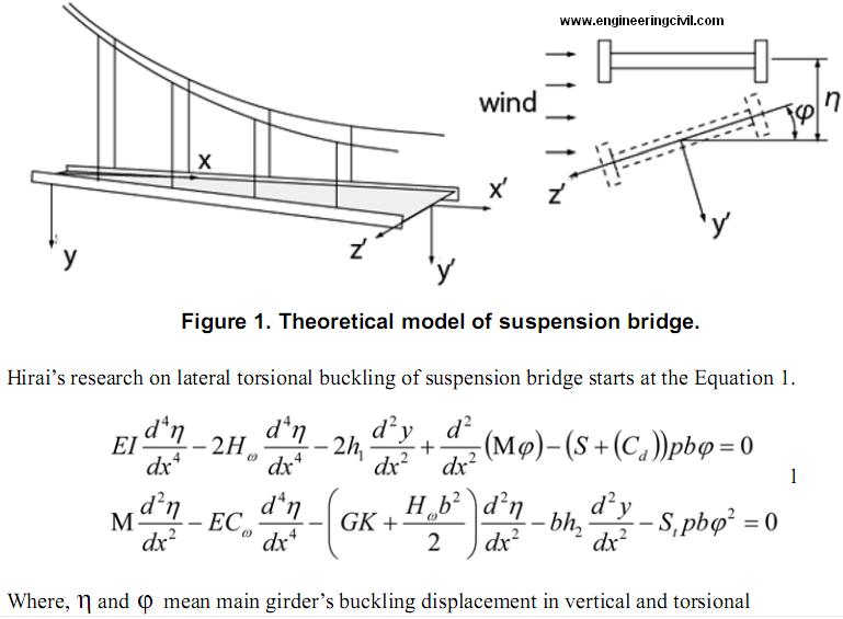
Lateral torsional buckling is critical for structures and can lead suddenly collapse of them. Previous research was conducted by Hirai(Hirai 1942) and Okauchi (Okauchi 1967). The main theory of their theory is showed as follows.
theoretical-model-suspension-bridge
displacements, respectively. EI,GK,ECw are bending stiffness, torsional stiffness and bending torsional stiffness, respectively. Hw is tension force of main cable applying the dead load and M is the moment of horizontal component occurred by drag force. CD is a coefficient of drag,S and St represent the gradient of lift force and gradient of pitching moment. h1 h2 indicate the increment of cable tension caused by the deformation of lateral torsional buckling and each of them can be calculated by the following equations.
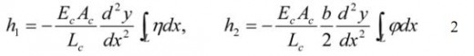
equation-2
Where, EcAc is the cable’s stiffness, and right side of integration is applied for whole length of the suspension bridge. y is the vertical coordinate of cable before deformation. Hirai added the inertia term in Equation 1 and investigated on the stability criteria of structures by arranging the multi-coordinate vibration equation. In these investigations, it was found that the criteria is the same of the one of lateral torsional buckling. The importance of the problem of lateral torsional buckling was emphasized at that time. The critical wind load equation is
critical wind load equation
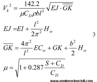
Because of the assumed boundary condition, the application of this equation is restricted to the single span suspension bridges. The application to the multi spans bridge and the different boundary conditions should have a problem. And also in the Equation 3, the transition of wind load to cable is not considered. As the pitching moment is the main component of lateral torsional buckling, the transition of wind load must had been considered in order to increase the accuracy of the equation.
These assumptions and ignorance should be removed in the modern analysis, because civil engineer should not rely on such a restriction of old theory but rely on comprehensive design method like Finite Element Method. In this study, the complicate FEM model was build and the above assumption and ignorance are eliminated. Therefore our study must be important to design the future bridges.
Target structure
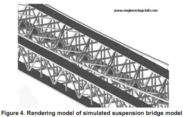
The application of large deformation and lateral torsional buckling analyses to long span suspension bridges are followed. One object of the analysis is Akashi Kaikyo Bridge; its center span is 1991m and is the longest in the world. The model is shown in Figure 2. In addition, we assembled the model of more lateral torsional buckling sensitive suspension bridge; the vertical brace made wider twice than the original Akashi Kaikyo Bridge. The two models are the objects of this chapter and we describe the details of them and the procedure of analysis.
Akashi Kaikyo bridge
Akashi Kaikyo bridge was completed in 1998 and is the world’s longest bridge. The main span is 1991 meters and the bridge has the stiffening truss girder. The outlines and some sections are showed in Figure 2.
Akashi Kaikyo bridge
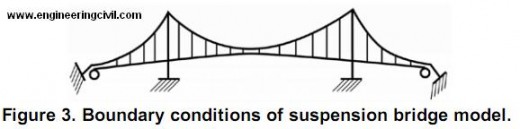
The main girder and tower are assigned beam element(B31H). The main cable and hanger cable are assigned truss element (T3D2H). The boundary conditions are showed in Figure 3. The towers and cable end are fixed, the girder ends are free in bridge direction (U1) but other degrees of freedom are fixed.
boundary-conditions-suspension-bridge
Simulated model of suspension bridge stiffened horizontally 
An another analysis was performed in this study. The main point of this analysis is to investigate how will act the simulated model of suspension bridge stiffened horizontally against wind force. The suspension bridge model was modifed by increasing the stiffness of upper and lower chords by widening the width of elements. The upper and lower chord’s width was made twice as wide as Akashi Kaikyo model. The drawing of model is shown in Figure 3.
Rendering model of simulated suspension bridge model
Except for the width of upper and lower chords modification, other parameters are all the same such as material, coordinates, and wind load.
Analysis procedure
The analysis procedure can be described as; bridges were applied the gravity at a first step, and bridges were applied the wind load at a second step. Each steps have high non linearity, which required the stabilization of damping factor. These details will be described afterward.
Gravity equilibrium 
At a frst step, suspension bridges should be in equilibrium under gravity. While this step the models are applied with gravity load, and deforms as the number of increment is increasing. The deformation is so large that the normal static analysis cannot complete solving the step. Therefore, in this step, the damping factor was added to accomplish the analysis. This option can be written,
*Static, stabilize=4e-09
01, 1., 1e-40, 1. 0.
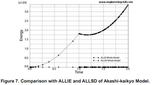
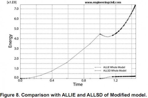
Of course, if the damping factor was added, the additional energy will act as factor which make analysis less accurate. Consequently, the comparison of ALLIE (total internal energy of structure) and ALLSD (total energy by damping factor) must be done. The comparison is done in chapter 5.
Applying Wind load
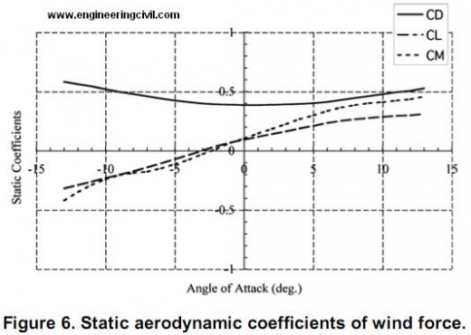
In the second step, the wind load is applied to the model. The three components of windfoce;pitching moment, drag force, and lift force are applied to elements. Each component is shown in Figure 7. The components of wind forces per unit span action on the deformed deck can be written,
motion of bridge deck and three components of wind force
The aerodynamic force applied to the wind-projected elements, which reflect the situation that the wind flows from one side horizontally. The magnitudes of wind forces are calculated by the Equation 4 and are applied after static analysis under gravity.
Static aerodynamic coefficients of wind force
Analysis results and considerations
Gravity analysis
In the first step, the energy by damping factor should be much less than the internal energy, as previously mentioned. The comparisons of these factor are shown in Figure 6 and Figure 7. These figures show that the additional energy by damping factor is sufficiently less than the internal energy of structure. We can conclude that the effect of additional damping factor is well ignorable.
Comparison with ALLIE and ALLSD of Akashi-kaikyo Model
Figure 8. Comparison with ALLIE and ALLSD of Modifed model
Analysis on the behaviors under aerodynamic forces.
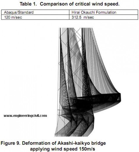
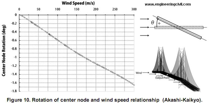
The large deformation analysis was done after under gravity analysis. The deformation figure and the relationship of rotational-displacement and wind speed are shown Figure 9 and Figure 10. Figure 9 shows the gradient increase of rotation of center node. The result represents the fact that the Akashi-Kaikyo Bridge doesn’t have the possibility of lateral torsional buckling but large deformation. If lateral torsional buckling occurs, the rotational displacement will increase suddenly, but this analysis doesn’t show such action. The reason of this is probably the suspension bridge’s stiffness of horizontal component is not greater than other stiffness components. While the simple beam analysis, the direction of applying load is the strong axes of the structure, but this suspension bridge is applied wind force horizontally and its horizontal stiffness is not so much strong.
On the other hand, the modified model’s behavior was different. Figure 10 shows the rotational displacement – wind speed relationship. It includes the lateral torsional behavior character that the rotational displacement increase suddenly.
Figure 9. Deformation of Akashi-kaikyo bridge applying wind
Figure 10. Rotation of center node and wind speed relationship
Considerations
In the problem of lateral torsional buckling, the balance of stiffness is very important. If the horizontal stiffness is small compared with other directional stiffness, the structure occurs only large deformation and if the one is large over some point, the structure occurs lateral torsional buckling.
In addition to the described analysis, we calculated the critical wind speed by Hirai Okauchi formulation. The parameters are shown in Table 1. This table represents the great reduction of critical wind speed. This means the previous theory is in danger side judgment.
Conclusions
In this paper lateral torsional buckling analysis by utilizing the Abaqus standard was demonstrated. The balance of horizontal stiffness is very important ant the over stiffness of that leads the structure lateral torsional buckling. However, it should be noted that the analysis’ results need more verification such as experiments: wind tunnel test. For continuing research, the critical balance of stiffness and other real suspension bridge analysis should be classified.
References
1. Memon Bashir-Ahmed, et al, “Arc-length technique for nonlinear fnite element analysis,” Journal of Zhejiang University SCIENCE Vol.5(5), pp. 618-628
2. Virote Boonyapinyo,T. Miyata, H. Yamada, “Nonlinear buckling instability analysis of long-span cable-stayedbridges under displacement-dependent wind load,” Journal of structural engineering, Vol.39A P923-935, 1993.
3. M.A.Crisfeld, “A Fast Incremental/Iterative Solution Procedure that Handles “Snap-Through””, Computers & Structures Vol.13, pp 55-62.
4. M.A.Crisfeld, “Snap-Through and Snap-Back Response in Concrete Structures and the Dangers of Under-Integration,” International Journal for Numerical Methods in Engineering,Vol. 22 pp. 751-767
5. M.Fafard , B.Massicotte, “Geometrical Interpretation of the Arc-Length Method”, Computers & Structures Vol.46, No.4, pp 603-615.
6. A.Hirai, “The stability of suspension bridges against torsional vibration,” Journal of Japan Society of Civil Engineers summery vol.28 pp 769-786, 1942.
7. A.Hirai, Y.Fujisawa “The effects of frequency of wind load to the elastic stability of suspension bridges” Journal of Japan Society of Civil Engineers summery vol.21 pp 85-1, 85-2,1966.
8. A.Hirai, H.Takema, “Lateral torsional buckling of suspension bridge under horizontal wind load” Journal of Japan Society of Civil Engineers summery vol.13 pp 19-20,1958.
9. Japan society of civil engineering and Honsyu-shikoku bridges technological workshop, “Report of honsyu-shikoku bridge technological survey appendix.1,”,1967.
10. J.H.Kweon, C.S.Hong , “An Improved Arc-Length Method for Postbuckling Analysis of Composite Cylindrical Panels,” Computers & Structures Vol. 53, No. 3, pp 541-549.
11. W.F.Lam, C.T.Morley, “Arc-length Method for Passing Limit Points in Structural Calculation” Journal of structural engineering Vol.118 No.1 P169-185.
12. Long pillar workshop, “Handbook of elastic stability,” Corona Publishing, 1960.
13. Mark J. Silver, et al, “Modeling of Snap-Back Bending Response of Doubly Slit Cylindrical Shells,” Structural Dynamics & Materials Conference, AIAA2004-1820.
14. K.Okauchi, K.Nemoto, “Lateral torsional buckling of suspension bridges under wind pressure,” Journal of Japan Society of Civil Engineers summery vol.22 pp 136-1, 136-4, 1967.
15. G.Powell, J.Simons, “Improved Iteration Strategy for Nonlinear Structures”, International Journal for Numerical Methods in Engineering,Vol17 PP1455-1467.
16. E.RAMM, “Strategies for Tracing Nonlinear Response Near Limit Points Non-linear finite element analysis in structural mechanics”, Springer-Verlag, New York.
17. E.Riks, “The Application of Newton’s Method to the Problem of Elastic Stability”, Journal of Applied Mechanics , Vol39 PP1060-1065.
18. E.Riks, “An Incremental Approach to the Solution of Snapping and Buckling Problem,” International Journal if Solids Structures, Vol.15, pp529-551.
19. H.Takema, K.Okauchi, “Lateral torsional buckling of suspension bridges under wind pressure,” Conference of bridge and structure workshop vol.11 ppp26-39, 1964.
20. Timocshenko, Gere, “Theory of elastic stability,” McGrawHill, 1961.
We are thankful to Sir Matthew Ladzinski for submitting this report to engineeringcivil.com and also granting us rights to publish it on web. This report will help all civil engineers study the Lateral Torsional Buckling of Long Span Suspension Bridge.

Load And Resistance Factor Design For Building Column


Load And Resistance Factor Design For Building Column


Plastic analysis of prismatic compression members in buildings is permitted if (Fy)½(l/r) does not exceed 800 and Fuless than equal to 65 ksi (448 MPa). For axially loaded members with b/t less than equal to (lambda)r , the maximum load Pu , ksi (MPa= 6.894 X ksi), may be computed from
Pu = 0.85AgFcr
Where Ag=gross cross-sectional area of the member
cr =0.658 lambda Fy for lambda <= 2.25
=0.877 Fy/lambda for lambda  > 2.25
lambda =(Kl/r)2(Fy/286,220)
The AISC specification for LRFD presents formulas for designing members with slender elements.

Allowable Stress Design For Building Beams


Allowable Stress Design For Building Beams


The maximum fiber stress in bending for laterally supported beams and girders is Fb = 0.66Fy if they are compact, except for hybrid girders and members with yield points exceeding 65 ksi (448.1 MPa). Fb = 0.60Fy for non-compact sections. Fy is the minimum specified yield strength of the steel, ksi (MPa). Table lists values of Fb for two grades of steel.
Yield strength,ksi (MPa)Compact0.66Fy(MPa)Non-compact,0.60 Fy (MPa)
36 ( 248.2)24 (165.5)22 (151.7)
50 (344.7)33 (227.5)30 (206.8)
The allowable extreme-fiber stress of 0.60Fy applies to laterally supported, unsymmetrical members, except channels, and to non-compact box sections. Compression on outer surfaces of channels bent about their major axis should not exceed 0.60Fy
The allowable stress of 0.66Fy for compact members should be reduced to 0.60Fy when the compression flange is unsupported for a length, in (mm), exceeding the smaller of
lmax=76.0bf/(Fy)½
lmax=20,000/Fyd/Af
where bf=width of compression flange, in (mm)
d=beam depth, in (mm)
Af =area of compression flange, in2(mm)2
The allowable stress should be reduced even more when l/rT exceeds certain limits, where l is the unbraced length, in (mm), of the compression flange, and rT is the radius of gyration, in (mm), of a portion of the beam consisting of the compression flange and one-third of the part of the web in compression.
Allowable Stress Design For Building Beams
Where Cb =modifier for moment gradient
When, however, the compression flange is solid and nearly rectangular in cross section, and its area is not less than that of the tension flange, the allowable stress may be taken as
Fb=12,000Cb/ld/Af
When Eq. applies (except for channels), Fb should be taken as the larger of the values computed from Eqs above, but not more than 0.60Fy .
The moment-gradient factor Cb in Eqs. above may be computed from
Cb=1.75 + 1.05 M1/M2+ 0.3(M1/M2)2 less than equal to 2.3
Where M1 = smaller beam end moment, and M2 = larger beam end moment.
The algebraic sign of M1/M2 is positive for double curvature bending and negative for single-curvature bending. When the bending moment at any point within an unbraced length is larger than that at both ends, the value of Cb should be taken as unity. For braced frames, Cb should be taken as unity for computation of Fbx and Fby .
Equations can be simplified by introducing a new term:
Q=(l/rT)2Fy
Now, for 0.2 less than equal to Q ess than equal to 1,
Fb=(2 – Q)Fy/3
For Q > 1:
Fb=Fy/ 3Q

Load And Resistance Factor Design For Building Beams


Load And Resistance Factor Design For Building Beams


For a compact section bent about the major axis, the unbraced length Lb of the compression flange, where plastic hinges may form at failure, may not exceed Lpd, given by Eqs. given in post. For beams bent about the minor axis and square and circular beams, Lb is not restricted for plastic analysis.

For I-shaped beams, symmetrical about both the major and the minor axis or symmetrical about the minor axis but with the compression flange larger than the tension flange, including hybrid girders, loaded in the plane of the web:
Load And Resistance Factor Design For Building Beams
Where Fyc=minimum yield stress of compression flange, ksi (MPa)
M1=smaller of the moments, in-kip (mm MPa) at the ends of the unbraced length of beam
Mp=plastic moment, in kip (mm MPa)
Ry=radius of gyration, in (mm), about minor axis
The plastic moment Mp equals FyZ for homogeneous sections, where Z = plastic modulus, in l3 (mm3) and for hybrid girders, it may be computed from the fully plastic distribution. M1/Mp is positive for beams with reverse curvature.
For solid rectangular bars and symmetrical box beams:
Load And Resistance Factor Design For Building Beams-2
The flexural design strength 0.90Mn is determined by the limit state of lateral-torsional buckling and should be calculated for the region of the last hinge to form and for regions not adjacent to a plastic hinge. The specification gives formulas for Mn that depend on the geometry of the section and the bracing provided for the compression flange.
For compact sections bent about the major axis, for example, Mn depends on the following unbraced lengths:
Lb=the distance, in (mm), between points braced against lateral displacement of the compression flange or between points braced to prevent twist
Lp=limiting laterally unbraced length, in (mm), for full plastic-bending capacity
=300ry/( Fyf)½ ; for I shape and channels
=3750(ry/Mp)/(JA)½ for solid rectangular bars and box beams
Fyf=flange yield stress, ksi (MPa)
J=torsional constant, in 4 (mm4) (see AISC “Manual of Steel Construction” on LRFD)
A=cross-sectional area, in 2(mm2 )
Lr =limiting laterally unbraced length, in (mm), for inelastic lateral buckling
For I-shaped beams symmetrical about the major or the minor axis, or symmetrical about the minor axis with the compression flange larger than the tension flange and channels loaded in the plane of the web:
Load And Resistance Factor Design For Building Beams-3
Where
Fyw=specified minimum yield stress of web, ksi (MPa)
Fr=compressive residual stress in flange
=10 ksi (68.9 MPa) for rolled shapes, 16.5 ksi (113.6 MPa), for welded sections
FL=smaller of Fyf- Fror Fyw
Fyf=specified minimum yield stress of flange, ksi (MPa)
E=elastic modulus of the steel
G=shear modulus of elasticity
Sx=section modulus about major axis, in 3 (mm3 ) (with respect to the compression flange if that flange is larger than the tension flange)
Cw=warping constant, in 6 (mm6) (see AISC manual on LRFD)
ly moment of inertia about minor axis, in4 (mm4 )
Load And Resistance Factor Design For Building Beams-4
For the previously mentioned shapes, the limiting buckling moment Mr, ksi (MPa), may be computed from
Mr= FL Sx
For compact beams with Lb <= Lr, bent about the major axis:
Load And Resistance Factor Design For Building Beams-5
Where
Cb=1.75+1.05(M1/M2)+0.3(M1/M2) <= 2.3, where M1 is the smaller and M2 the larger end moment in the unbraced segment of the beam; M1/M 2 is positive for reverse curvature and equals 1.0 for unbraced cantilevers and beams with moments over much of the unbraced segment equal to or greater than the larger of the segment end moments.
For solid rectangular bars bent about the major axis:
Load And Resistance Factor Design For Building Beams-6
and the limiting buckling moment is given by:
Mr=FySx
For compact beams with Lb> Lr, bent about the major axis:
Load And Resistance Factor Design For Building Beams-7
For determination of the flexural strength of noncompact plate girders and other shapes not covered by the preceding requirements, see the AISC manual on LRFD.